
What is Electrical Grounding?
Electrical Grounding is a planned connection between an electrical system, equipment, or circuit and the earth or a grounding conductor. The connection gives fault current a low-impedance path. Helping protective devices operate quickly. Grounding also helps limit dangerous voltage on metal parts, reducing shock, fire, and equipment damage risks during faults or surges.
Quick Facts About Electrical Grounding
Category
Electrical safety and circuit protection
Used for
Fault-current paths, shock reduction, and surge control
Common confusion
Grounding is different from bonding
Also called
Grounding, Electrical Earthing
Often discussed with
Emergency Electrical Inspections, Electrical Code Corrections
Key Takeaways About Electrical Grounding
- Grounding directs fault current away from people and toward a safe return path.
- Grounding and bonding work together. But they are not the same electrical function.
- A ground rod alone does not replace proper equipment grounding conductors.
- Loose, damaged, or missing grounding connections can leave metal equipment energized.
- Testing must examine continuity, connections, polarity, and the complete electrical system.
Understanding Electrical Grounding
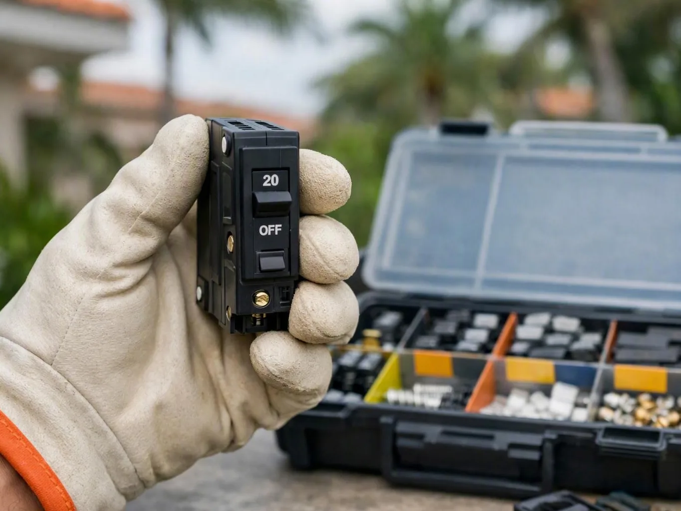
Electrical Grounding connects an electrical system or exposed metal equipment to earth. It connects equipment to a designated grounding conductor. This connection helps control voltage during normal operation. It provides a path for fault current when insulation fails. A fault can occur if a hot wire touches a metal appliance case, panel enclosure, or junction box.
Related glossary terms: Electrical Bonding, Ground Fault Circuit Interrupter, Electrical Resistance.
Grounding is part of a larger protection system. This system also includes electrical bonding, circuit breakers, fuses, and grounding-type receptacles. Grounding connects a system to earth or a grounding path. Bonding connects conductive metal parts at nearly the same voltage. Neither function replaces the other. A ground rod doesn't replace an equipment grounding conductor.
How Electrical Grounding Works, Is Measured, or Is Used?
During a ground fault, current should travel through a low-impedance fault-current path. This path returns current to the source. It allows a circuit breaker or fuse to open the circuit quickly. In a typical branch circuit, the equipment grounding conductor connects receptacle grounds, metal boxes, and appliance frames. It returns them to the electrical panel. The grounding and bonding arrangement connects this path to the source.
Electricians evaluate grounding by checking continuity, conductor connections, polarity, and grounding electrodes. They also check the condition of these electrodes. Common tools include a multimeter, receptacle tester, clamp meter, and specialized impedance or ground-resistance tester. A resistance reading alone doesn't prove a complete fault-current path exists. A system can have a ground rod but lack a properly connected equipment grounding conductor.
The required arrangement depends on the service type, wiring method, building age, and electrical code. Grounding electrodes may include driven rods, concrete-encased electrodes, or metal water pipe electrodes. Other approved systems may also serve this purpose. The grounding electrode system helps stabilize voltage relative to earth. It also dissipates certain surges. Equipment grounding conductors help carry fault current back to the source.
Why Electrical Grounding Matters?
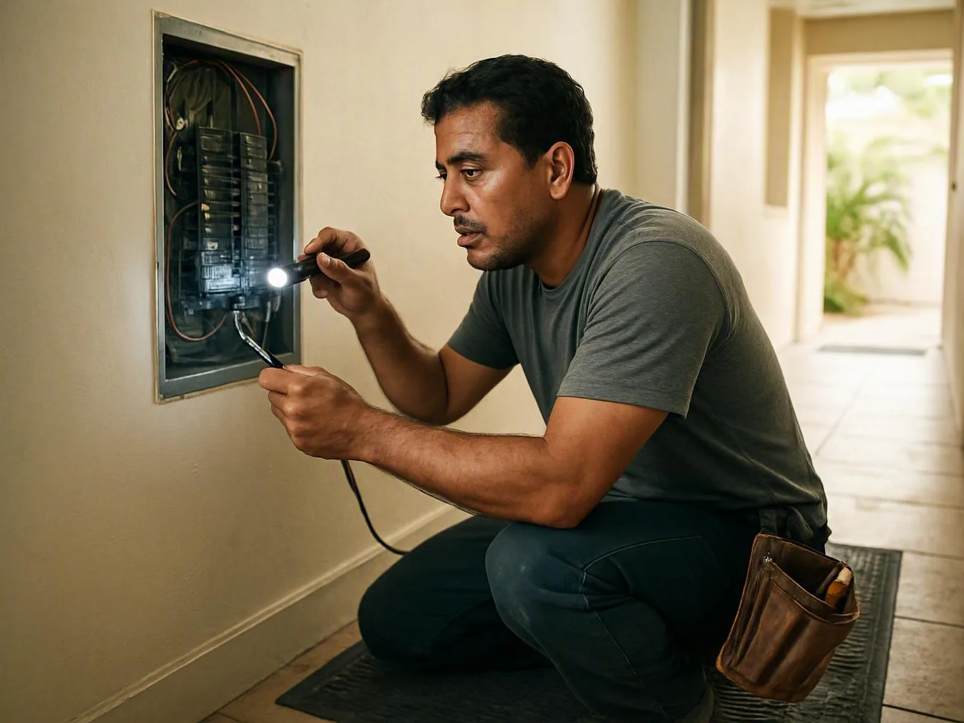
Proper grounding reduces the chance that a person becomes the path for fault current. If a metal enclosure becomes energized. A working equipment grounding path can create enough current. This current can trip the protective device. Without that path, the enclosure may stay energized. The breaker may stay closed, creating a serious shock hazard.
Grounding also supports protection against some electrical surges. It helps reduce damage to connected equipment. It doesn't stop every surge or prevent all lightning damage. It doesn't replace a surge protective device. Grounding speed depends on correct conductor sizing, tight terminations, and sound connections. It also depends on a complete system from the equipment back to the source.
When Electrical Grounding Matters Most?
Grounding deserves close attention during electrical repairs, service upgrades, panel replacement, generator installation, and older building work. Renovations can uncover two-slot receptacles, reversed polarity, open grounds, damaged cables, or improvised connections. Water exposure, corrosion, storm damage, and loose panel terminations can also weaken the fault-current path.
Warning signs include tingling from a metal appliance, repeated breaker trips, sparks at receptacles, or flickering after a fault. A tester may also report an open ground. Don't treat a three-slot receptacle as proof of grounding. Someone may have installed it without a connected grounding conductor. A qualified inspection should trace the circuit and verify connections. It should correct unsafe wiring before normal use continues.
How to Evaluate Electrical Grounding?
- Check whether every grounding conductor has continuity from the equipment to the correct panel termination.
- Verify that receptacle testers show correct polarity and do not report an open ground.
- Inspect panels, boxes, and terminations for corrosion, loose screws, overheating, or damaged conductors.
- Confirm that grounding electrode connections match the applicable electrical code and service design.
- Ask whether a ground rod is being mistaken for a complete equipment grounding path.
Related Concepts Compared
Electrical Grounding vs. Electrical Bonding
Bonding joins metal parts so they remain at nearly the same voltage and can carry fault current together. Grounding connects the system or equipment to earth or a designated grounding path.
Electrical Grounding vs. Ground Fault Circuit Interrupter
A GFCI detects a small difference between outgoing and returning current, then disconnects power quickly. GFCI protection can reduce shock risk, but it does not create a missing grounding path.
Electrical Grounding vs. Ground Rod
A ground rod is one type of grounding electrode connected to earth. A rod does not replace the equipment grounding conductor needed to clear many line-to-case faults.
Expert Note
A low ground-resistance reading does not prove that a branch circuit is safe. The fault path must remain continuous from the equipment frame to the source, and protective devices must be correctly sized and connected.
Common Mistakes or Myths About Electrical Grounding
- Assuming a ground rod alone protects every branch circuit.
- Installing a three-slot receptacle where no equipment grounding conductor exists.
- Connecting neutral and ground together in an improper downstream panel.
- Ignoring corrosion or loose grounding connections after flooding or storm damage.
- Treating a plug-in tester as a complete grounding inspection.
Electrical Grounding in Practice: A Real-World Example
A washing machine develops an insulation fault that energizes its metal cabinet. With a continuous equipment grounding conductor, fault current returns to the panel and trips the breaker. If the grounding conductor is disconnected. The cabinet may stay energized until a person provides the return path.
Sources & Further Reading on Electrical Grounding
Related Terms
Electrical Bonding
Electrical Bonding is the practice of connecting metal parts of an electrical system with conductive paths…
Ground Fault Circuit Interrupter
Ground Fault Circuit Interrupter is a protective device that shuts off electrical power when current takes…
Electrical Resistance
Electrical Resistance is the opposition a material or component presents to electric current. Resistance limits current…
Electrical Code
Electrical Code is a set of safety rules for designing, installing, inspecting, and maintaining electrical systems…
Earth Electric Florida
Have Questions About Electrical Grounding?
Contact Earth Electric Florida for practical guidance on Electrical Grounding and related emergency electrician work in Miami.