
What is Electrical Resistance?
Electrical Resistance is the opposition a material or component presents to electric current. Resistance limits current flow and changes electrical energy into heat. The measurement unit's the ohm, represented by the symbol Ω. Resistance depends on material, length, cross-sectional area, and temperature. Higher resistance allows less current at the same voltage.
Quick Facts About Electrical Resistance
Category
Electrical property
Formula
R = V ÷ I
Measured by
Ohm, represented by Ω
Typical tool
Digital multimeter
Common confusion
Resistance is not the same as voltage or current
Also called
Ohmic resistance, Resistance
Key Takeaways About Electrical Resistance
- Resistance limits current, while voltage pushes current through a circuit.
- The ohm measures how strongly a material opposes electrical current.
- Longer, thinner wires usually have more resistance than shorter, thicker wires.
- Loose connections can create unwanted resistance, heat, and equipment damage.
- Technicians measure resistance with power disconnected from the circuit.
Understanding Electrical Resistance

Electrical Resistance describes how strongly a material or device opposes electric charge movement. Copper wire has low resistance, so it carries current well. Rubber and plastic have very high resistance. These materials help insulate conductors. Resistance affects current flow, heat, voltage drop, and equipment performance.
Related glossary terms: Ohm, Ohm's Law, Voltage Drop.
Resistance is measured in ohms, shown by the symbol Ω. A resistor may limit current in a circuit. Resistance at a loose terminal or damaged wire is usually unwanted. The same circuit can contain useful and harmful resistance. Temperature, wire length, wire size, and material affect the measured value.
How Electrical Resistance Works, Is Measured, or Is Used?
Ohm's Law relates resistance to voltage and current. The formula is R = V ÷ I. In this formula, R means resistance in ohms. V means voltage in volts. I means current in amperes. A 120-volt load drawing 10 amperes has 12 ohms of resistance. This applies under those operating conditions. If resistance rises while voltage stays constant, current generally falls.
A technician measures resistance with a digital multimeter set to the ohms function. Power must be disconnected before a resistance test. Live voltage can damage the meter and cause shock. The technician isolates the component when needed. Then, the technician places the probes across the test points. The technician compares the reading with the expected value. A near-zero reading may indicate a short. An unusually high reading may indicate an open circuit or broken conductor.
Wire design also depends on resistance. A longer conductor has more resistance. A larger conductor has less resistance. This applies when material and temperature stay similar. The American Wire Gauge system identifies wire sizes. Smaller AWG numbers represent larger conductors. Designers account for resistance because high resistance can cause voltage drop and unwanted heat.
Why Electrical Resistance Matters?
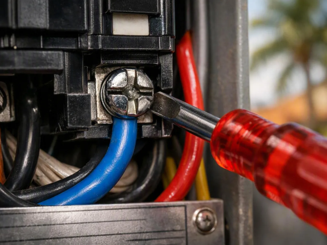
Resistance helps explain poor circuit operation. A circuit may show normal voltage but still work poorly. A corroded connection or loose terminal can add resistance at one small point. Current passing through that point creates heat. The relationship is P = I²R. P means power in watts. High current makes even a small resistance increase a serious heating concern.
Correct resistance supports safe operation and steady performance. Excessive resistance can dim lights, slow motors, trip protective devices, damage terminals, or create a burning odor. Very low resistance between conductors can produce a short circuit. This can cause rapid current flow. Overcurrent protection helps limit damage, but it doesn't repair a weak connection or damaged conductor.
When Electrical Resistance Matters Most?
Resistance matters during troubleshooting, circuit installation, and equipment testing. A technician may check a cable for continuity. They may test a heating element or inspect a motor winding. They may compare a grounding path with expected results. Resistance readings become more useful when technicians record the test points. They should also record circuit condition and maker specifications.
Resistance also matters after flooding, storms, overheating, or visible corrosion. Moisture can create unwanted paths between conductors. It can also damage insulation, terminals, and equipment. In Miami, salt air and high humidity can speed corrosion in exposed electrical parts. A qualified electrician may need to isolate damaged circuits. They may verify safe conditions and fix the main fault before restoring power.
How to Evaluate Electrical Resistance?
- Confirm that power is disconnected before measuring resistance with a multimeter.
- Compare the measured ohm value with the equipment manufacturer’s specification.
- Inspect terminals for looseness, corrosion, discoloration, melting, or heat damage.
- Check voltage drop on long runs or heavily loaded circuits.
- Ask whether the test isolates the component or includes parallel circuit paths.
Related Concepts Compared
Electrical Resistance vs. Electrical Current
Electrical current is the movement of electric charge, measured in amperes. Electrical resistance opposes that movement and helps determine how much current flows.
Electrical Resistance vs. Voltage
Voltage is the electrical potential difference that pushes current through a circuit. Resistance limits the current produced by that voltage.
Electrical Resistance vs. Impedance
Impedance is the total opposition to current in an alternating-current circuit. It includes resistance plus effects from inductance and capacitance.
Electrical Resistance vs. Continuity
Continuity is a test result showing that a conductive path exists. A continuity test does not always identify the exact resistance or prove that the path is safe under load.
Expert Note
A resistance reading is meaningful only when you know what the meter is testing. Parallel paths can produce a misleadingly low value, while temperature can change component resistance. Isolate the component and follow its service data before judging the result.
Common Mistakes or Myths About Electrical Resistance
- Measuring resistance on an energized circuit can damage the meter and create a shock hazard.
- A continuity beep does not prove that a conductor can safely carry its rated load.
- Replacing a breaker does not correct resistance caused by a loose or corroded connection.
- A zero-ohm reading across an intended load may indicate a short circuit.
Electrical Resistance in Practice: A Real-World Example
A 120-volt heating element measures 24 ohms when disconnected from the circuit. Ohm’s Law predicts about 5 amperes during operation, so the element uses about 600 watts. A loose terminal could add resistance at the connection and create damaging heat.
Sources & Further Reading on Electrical Resistance
- National Institute of Standards and Technology, SI Units
- OpenStax, College Physics 2e, Ohm’s Law
Related Terms
Ohm
Ohm is the SI unit of electrical resistance. One ohm describes a circuit or component that…
Ohm's Law
Ohm's Law is the relationship between voltage, current, and electrical resistance in a circuit. The law…
Voltage Drop
Voltage Drop is the reduction in electrical potential that occurs as current travels through a wire…
Copper Wiring
Copper Wiring is electrical conductors made from copper strands or solid copper cores that carry electric…
Earth Electric Florida
Have Questions About Electrical Resistance?
Contact Earth Electric Florida for practical guidance on Electrical Resistance and related emergency electrician work in Miami.